Applying IDEF0
Jul 10, 2014
We have used the IDEF0 diagram for a variety of different products over the course of many development efforts. These efforts include development of the first operational architecture for cyber-operations for Naval Network Warfare Command, Information Operations activity models for USS Zumwalt (DDG-1000) and for software development efforts including the development of Princeton Satellite Systems’ ControlPlan under an SBIR for Navy PEO Space.
There are six types of Integrated DEFinition Methods. The IDEF0 is a method used to graphically model activities, actions and decisions. It has a simple construct that has an effective methodology to decompose, associate and clarify activities, their relationships and their information needs.
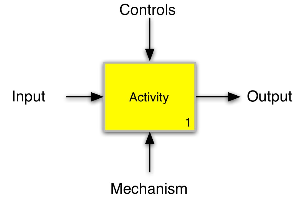
The basic element of an IDEF0 is shown in the figure on the right. The inputs enter on the left, and outputs leave on the right. The information entering the top of the box is associated with controls or constraints on the activity. The arrow from the bottom describes mechanisms that are used by the activity; examples are hardware, software or people.
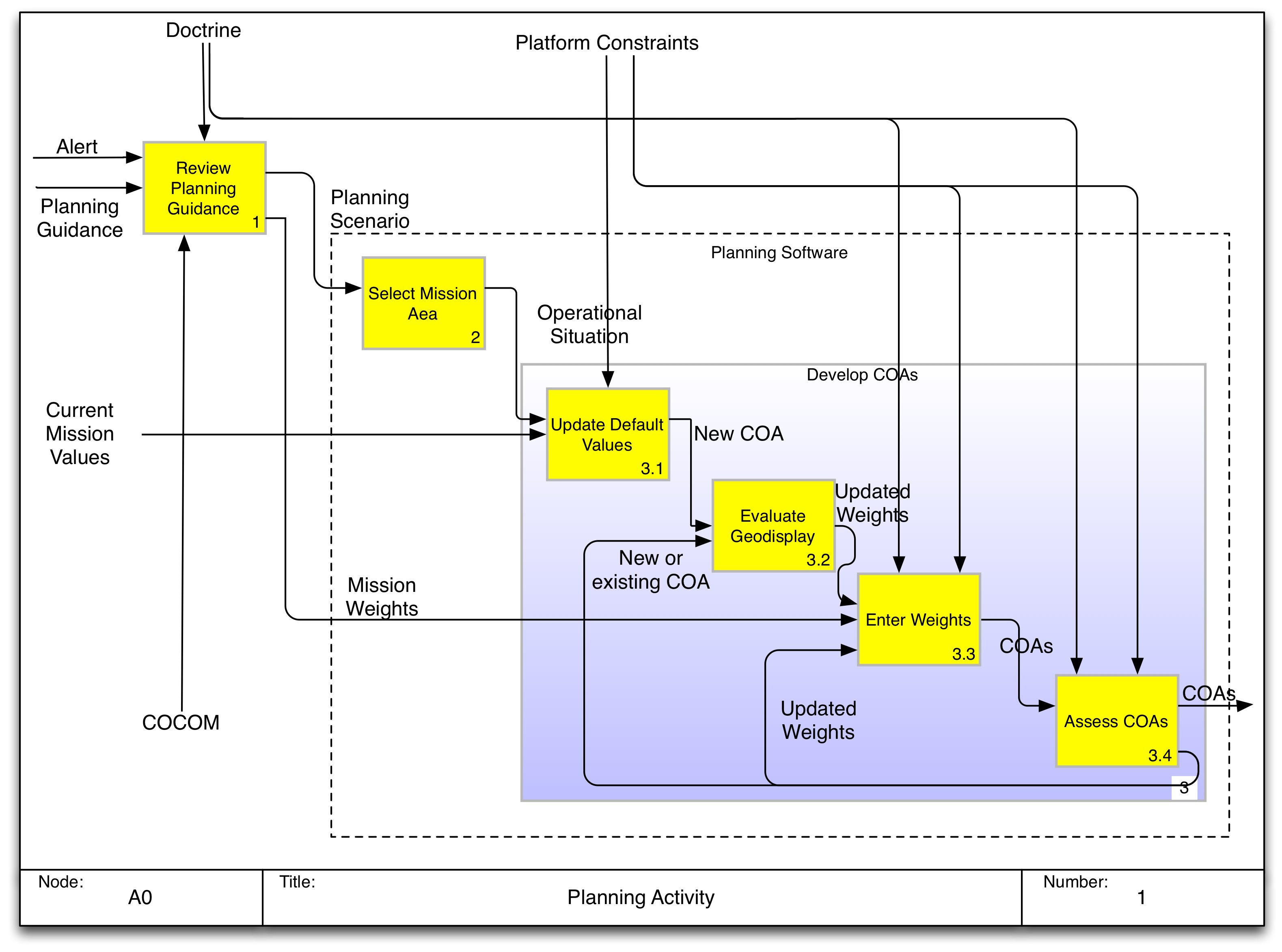
The IDEF0 uses a hierarchical construct, the A0 node is the highest level of definition and it contains the first level (i.e. A1, A2, etc.). Levels within these nodes are listed as A1.1, A1.2, etc. In the diagram above we show nodes A1, A2 and A3 and we show the activities within A3 (A3.1 through A3.4). Normally, this lower level set of activities is shown on a separate page, but for simplicity we combined the two diagrams.
The IDEF0 is not necessarily sequential and is independent of time. Although it has a right to left flow that accommodates the arrow rules for the activity box, the behavior is asynchronous. The benefit to the IDEF0 is its compactness in communicating many important elements of a complex set of activity.
As an example, the diagram above shows the basic elements of using ControlPlan in developing optimized plans. The essential part of the software is to produce courses of action (COAs), which is highlighted. The dashed line shows the bounds of the software’s activity and is very closely linked to the set of UML Use Cases that we created as part of the design. The planning phase begins with an User Review(ing) Planning Guidance and the selection of an operational situation (OPSIT) within space mission area. The COA development proceeds iteratively with Platform Constraints and Doctrine acting as controls on the planning.
This diagram was useful for communicating the design to the software developers and to the stakeholders for the SBIR effort, including our technical point of contact and military planners. The diagram is easy to construct as we have used Microsoft PowerPoint, OmniGraffle (used to create this diagram) and software packages expressly designed to create IDEF0 diagrams within the DoD Architecture Framework (DoDAF) and the Unified Modeling Language.